SCB12 Dry-Type Transformer for 10 kV & 35 kV Networks
Resin-insulated dry-type transformer for indoor distribution.
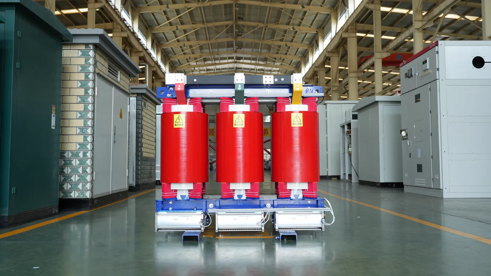
Key facts
Resin-insulated dry-type transformer for indoor distribution.
- 10 kV & 35 kV published voltage classes
- Off-circuit tap changing
- Epoxy resin insulation
- 30–2,500 kVA across the published tables
- Voltage class
- 10 kV & 35 kV
- Frequency
- 50 Hz
- Installation
- Indoor
Published normal service conditions: −25 °C to +40 °C; altitude below 1,000 m. Specify site conditions in your enquiry.
Request datasheetTechnical parametersLead time confirmed per order.
Technical parameters
Scroll each table horizontally on smaller screens. Values below are from the factory’s product document; confirm the final configuration with the technical team.
| Rated capacity (kVA) | No-load loss (kW) | Load loss at 120 °C (kW) | No-load current (%) | Impedance (%) |
|---|---|---|---|---|
| 30 | 0.15 | 0.71 | 2.0 | 4.0 |
| 50 | 0.215 | 1.00 | 2.0 | 4.0 |
| 80 | 0.295 | 1.38 | 1.5 | 4.0 |
| 100 | 0.32 | 1.57 | 1.5 | 4.0 |
| 125 | 0.375 | 1.85 | 1.3 | 4.0 |
| 160 | 0.43 | 2.13 | 1.3 | 4.0 |
| 200 | 0.495 | 2.53 | 1.1 | 4.0 |
| 250 | 0.575 | 2.76 | 0.9 | 4.0 |
| 315 | 0.705 | 3.47 | 0.8 | 4.0 |
| 400 | 0.785 | 3.99 | 0.8 | 4.0 |
| 500 | 0.93 | 4.88 | 0.8 | 4.0 |
| 630 | 1.04 | 5.96 | 0.7 | 6.0 |
| 800 | 1.21 | 6.96 | 0.7 | 6.0 |
| 1000 | 1.41 | 8.13 | 0.7 | 6.0 |
| 1250 | 1.67 | 9.69 | 0.7 | 6.0 |
| 1600 | 1.96 | 11.7 | 0.7 | 6.0 |
| 2000 | 2.44 | 14.4 | 0.6 | 6.0 |
| 2500 | 2.88 | 17.1 | 0.6 | 6.0 |
| Rated capacity (kVA) | High voltage (kV) | HV tapping range (source notation) | Low voltage (kV) | Connection group |
|---|---|---|---|---|
| 30 | 6 / 6.3 / 10 / 10.5 / 11 | ±5%or ±2×2.5% | 0.4 | Yyn0 / Dyn11 |
| 50 | 6 / 6.3 / 10 / 10.5 / 11 | ±5%or ±2×2.5% | 0.4 | Yyn0 / Dyn11 |
| 80 | 6 / 6.3 / 10 / 10.5 / 11 | ±5%or ±2×2.5% | 0.4 | Yyn0 / Dyn11 |
| 100 | 6 / 6.3 / 10 / 10.5 / 11 | ±5%or ±2×2.5% | 0.4 | Yyn0 / Dyn11 |
| 125 | 6 / 6.3 / 10 / 10.5 / 11 | ±5%or ±2×2.5% | 0.4 | Yyn0 / Dyn11 |
| 160 | 6 / 6.3 / 10 / 10.5 / 11 | ±5%or ±2×2.5% | 0.4 | Yyn0 / Dyn11 |
| 200 | 6 / 6.3 / 10 / 10.5 / 11 | ±5%or ±2×2.5% | 0.4 | Yyn0 / Dyn11 |
| 250 | 6 / 6.3 / 10 / 10.5 / 11 | ±5%or ±2×2.5% | 0.4 | Yyn0 / Dyn11 |
| 315 | 6 / 6.3 / 10 / 10.5 / 11 | ±5%or ±2×2.5% | 0.4 | Yyn0 / Dyn11 |
| 400 | 6 / 6.3 / 10 / 10.5 / 11 | ±5%or ±2×2.5% | 0.4 | Yyn0 / Dyn11 |
| 500 | 6 / 6.3 / 10 / 10.5 / 11 | ±5%or ±2×2.5% | 0.4 | Yyn0 / Dyn11 |
| 630 | 6 / 6.3 / 10 / 10.5 / 11 | ±5%or ±2×2.5% | 0.4 | Yyn0 / Dyn11 |
| 800 | 6 / 6.3 / 10 / 10.5 / 11 | ±5%or ±2×2.5% | 0.4 | Yyn0 / Dyn11 |
| 1000 | 6 / 6.3 / 10 / 10.5 / 11 | ±5%or ±2×2.5% | 0.4 | Yyn0 / Dyn11 |
| 1250 | 6 / 6.3 / 10 / 10.5 / 11 | ±5%or ±2×2.5% | 0.4 | Yyn0 / Dyn11 |
| 1600 | 6 / 6.3 / 10 / 10.5 / 11 | ±5%or ±2×2.5% | 0.4 | Yyn0 / Dyn11 |
| 2000 | 6 / 6.3 / 10 / 10.5 / 11 | ±5%or ±2×2.5% | 0.4 | Yyn0 / Dyn11 |
| 2500 | 6 / 6.3 / 10 / 10.5 / 11 | ±5%or ±2×2.5% | 0.4 | Yyn0 / Dyn11 |
Slash-separated entries are alternatives. Tapping notation is retained from the source; where a percent sign or value is absent, request confirmation before selection.
| Rated capacity (kVA) | No-load loss (kW) | Load loss at 120 °C (kW) | No-load current (%) | Impedance (%) |
|---|---|---|---|---|
| 50 | 0.405 | 1.42 | 2.1 | 6.0 |
| 100 | 0.565 | 2.09 | 1.8 | 6.0 |
| 160 | 0.71 | 2.81 | 1.4 | 6.0 |
| 200 | 0.79 | 3.32 | 1.4 | 6.0 |
| 250 | 0.89 | 3.80 | 1.2 | 6.0 |
| 315 | 1.05 | 4.51 | 1.2 | 6.0 |
| 400 | 1.23 | 5.41 | 1.0 | 6.0 |
| 500 | 1.45 | 6.65 | 1.0 | 6.0 |
| 630 | 1.67 | 7.69 | 0.9 | 6.0 |
| 800 | 1.94 | 9.12 | 0.9 | 6.0 |
| 1000 | 2.18 | 10.4 | 0.7 | 6.0 |
| 1250 | 2.54 | 12.7 | 0.7 | 6.0 |
| 1600 | 2.91 | 15.4 | 0.7 | 6.0 |
| 2000 | 3.43 | 18.2 | 0.7 | 6.0 |
| 2500 | 4.00 | 21.8 | 0.7 | 6.0 |
| Rated capacity (kVA) | High voltage (kV) | HV tapping range (source notation) | Low voltage (kV) | Connection group |
|---|---|---|---|---|
| 50 | 35 / 36 / 37 / 38.5 | ±5 / ±2×2.5 | 0.4 | Dyn11 / Yyn0 |
| 100 | 35 / 36 / 37 / 38.5 | ±5 / ±2×2.5 | 0.4 | Dyn11 / Yyn0 |
| 160 | 35 / 36 / 37 / 38.5 | ±5 / ±2×2.5 | 0.4 | Dyn11 / Yyn0 |
| 200 | 35 / 36 / 37 / 38.5 | ±5 / ±2×2.5 | 0.4 | Dyn11 / Yyn0 |
| 250 | 35 / 36 / 37 / 38.5 | ±5 / ±2×2.5 | 0.4 | Dyn11 / Yyn0 |
| 315 | 35 / 36 / 37 / 38.5 | ±5 / ±2×2.5 | 0.4 | Dyn11 / Yyn0 |
| 400 | 35 / 36 / 37 / 38.5 | ±5 / ±2×2.5 | 0.4 | Dyn11 / Yyn0 |
| 500 | 35 / 36 / 37 / 38.5 | ±5 / ±2×2.5 | 0.4 | Dyn11 / Yyn0 |
| 630 | 35 / 36 / 37 / 38.5 | ±5 / ±2×2.5 | 0.4 | Dyn11 / Yyn0 |
| 800 | 35 / 36 / 37 / 38.5 | ±5 / ±2×2.5 | 0.4 | Dyn11 / Yyn0 |
| 1000 | 35 / 36 / 37 / 38.5 | ±5 / ±2×2.5 | 0.4 | Dyn11 / Yyn0 |
| 1250 | 35 / 36 / 37 / 38.5 | ±5 / ±2×2.5 | 0.4 | Dyn11 / Yyn0 |
| 1600 | 35 / 36 / 37 / 38.5 | ±5 / ±2×2.5 | 0.4 | Dyn11 / Yyn0 |
| 2000 | 35 / 36 / 37 / 38.5 | ±5 / ±2×2.5 | 0.4 | Dyn11 / Yyn0 |
| 2500 | 35 / 36 / 37 / 38.5 | ±5 / ±2×2.5 | 0.4 | Dyn11 / Yyn0 |
Slash-separated entries are alternatives. Tapping notation is retained from the source; where a percent sign or value is absent, request confirmation before selection.
Cooling: natural air (AN); forced-air options should be confirmed for the intended duty. Request voltage combinations, tapping range and connection group for your selected rating.